古河電工ネットワーク機器の総合ブランド ファイテルネット

設定例
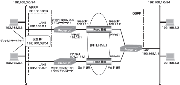
センタ側は機器冗長し拠点側は1台に2回線接続する
インターネット回線冗長時のVPNバックアップ設定
インターネット回線冗長時のVPNバックアップ設定
F200,F2000
説明
VRRPを使用してRouter_A、Router_Bの機器冗長と回線冗長を行います。
対向装置(Router_C)では2回線を使用する回線冗長を行います。
経路切替にはOSPFとスタティック経路を組合せます。
回線は全てPPPoE回線で接続し、VPNを使った構成です。
各Router配下の端末からインターネットへの通信は、NAT機能を利用して直接アクセスできる設定です。
対向装置(Router_C)では2回線を使用する回線冗長を行います。
経路切替にはOSPFとスタティック経路を組合せます。
回線は全てPPPoE回線で接続し、VPNを使った構成です。
各Router配下の端末からインターネットへの通信は、NAT機能を利用して直接アクセスできる設定です。
構成
コマンド設定
Router A
ip route 0.0.0.0 0.0.0.0 pppoe 1
ip route 0.0.0.0 0.0.0.0 192.168.0.2 150
ip route 192.168.1.0 255.255.255.0 192.168.0.2 150
ip vrrp enable
access-list 1 permit 192.168.0.0 0.0.0.255
proxydns mode v4
vpn enable
vpnlog enable
ipsec access-list 1 ipsec ip any any
ipsec access-list 64 bypass ip any any
ipsec transform-set aes256-sha esp-aes-256 esp-sha-hmac
hostname Router_A
interface ipsecif 1
 crypto map Router_A
 ip ospf network point-to-point
 ip address 100.1.1.1 255.255.255.0
 ip mtu 1500
exit
interface lan 1
 ip address 192.168.0.1 255.255.255.0
 vrrp 1 address 192.168.0.254
 vrrp 1 priority 200
 vrrp 1 preempt
exit
interface pppoe 1
 ip address 192.0.2.1
 ip nat inside source list 1 interface
 pppoe server internet
 pppoe account ********@***.***.ne.jp ******
 pppoe type lan
exit
crypto isakmp policy 1
 authentication prekey
 group 5
 hash sha
 keepalive always-send
 key ascii secret1
 negotiation-mode aggressive
 peer-identity host Router_C
exit
crypto map Router_A 1
 match address 1
 set peer host Router_C
 set pfs group5
 set transform-set aes256-sha
exit
router ospf
 network 100.1.1.0 0.0.0.255 area 0
 redistribute connected
 router-id 192.168.0.1
exit
end
Router B
ip route 0.0.0.0 0.0.0.0 pppoe 1
ip route 192.168.1.0 255.255.255.0 connected ipsecif 1
ip vrrp enable
access-list 1 permit 192.168.0.0 0.0.0.255
proxydns mode v4
vpn enable
vpnlog enable
ipsec access-list 1 ipsec ip any any
ipsec access-list 64 bypass ip any any
ipsec transform-set aes256-sha esp-aes-256 esp-sha-hmac
hostname Router_B
interface ipsecif 1
 crypto map Router_B
 ip mtu 1500
exit
interface lan 1
 ip address 192.168.0.2 255.255.255.0
 vrrp 1 address 192.168.0.254
 vrrp 1 priority 100
 vrrp 1 preempt
exit
interface pppoe 1
 ip address 203.0.113.1
 ip nat inside source list 1 interface
 pppoe server internet
 pppoe account ********@***.***.ne.jp ******
 pppoe type lan
exit
crypto isakmp policy 1
 authentication prekey
 group 5
 hash sha
 keepalive always-send
 key ascii secret1
 negotiation-mode aggressive
 peer-identity host Router_C
exit
crypto map Router_B 1
 match address 1
 set peer host Router_C
 set pfs group5
 set transform-set aes256-sha
exit
end
Router C
ip route 0.0.0.0 0.0.0.0 pppoe 1
ip route 0.0.0.0 0.0.0.0 pppoe 2 150
ip route 192.0.2.1 255.255.255.255 pppoe 1
ip route 192.168.0.0 255.255.255.0 connected ipsecif 2 150
ip route 203.0.113.1 255.255.255.255 pppoe 2
access-list 1 permit 192.168.1.0 0.0.0.255
proxydns mode v4
vpn enable
vpnlog enable
ipsec access-list 1 ipsec ip any any
ipsec access-list 2 ipsec ip any any
ipsec access-list 64 bypass ip any any
ipsec transform-set aes256-sha esp-aes-256 esp-sha-hmac
service dhcp-server
hostname Router_C
ip dhcp pool lan 1
 dns-server 0.0.0.0
 default-router 0.0.0.0
exit
interface ipsecif 1
 crypto map Router_A
 ip ospf network point-to-point
 ip address 100.1.1.2 255.255.255.0
 ip mtu 1500
exit
interface ipsecif 2
 crypto map Router_B
 ip mtu 1500
exit
interface lan 1
 ip address 192.168.1.1 255.255.255.0
exit
interface pppoe 1
 ip nat inside source list 1 interface
 pppoe server internet1
 pppoe account ********@***.***.ne.jp ******
 pppoe type host
 pppoe interface ewan 1
exit
interface pppoe 2
 ip nat inside source list 1 interface
 pppoe server internet2
 pppoe account ********@***.***.ne.jp ******
 pppoe type host
 pppoe interface ewan 2
exit
crypto isakmp policy 1
 authentication prekey
 group 5
 hash sha
 keepalive always-send
 key ascii secret1
 my-identity Router_C
 negotiation-mode aggressive
 peer-identity address 192.0.2.1
exit
crypto isakmp policy 2
 authentication prekey
 group 5
 hash sha
 keepalive always-send
 key ascii secret1
 my-identity Router_C
 negotiation-mode aggressive
 peer-identity address 203.0.113.1
exit
crypto map Router_A 1
 match address 1
 set peer address 192.0.2.1
 set pfs group5
 set transform-set aes256-sha
exit
crypto map Router_B 2
 match address 2
 set peer address 203.0.113.1
 set pfs group5
 set security-association always-up
 set transform-set aes256-sha
exit
router ospf
 network 100.1.1.0 0.0.0.255 area 0
 redistribute connected
 router-id 192.168.1.1
exit
end
設定手順
Router A
| 設定内容 | 画面表示例 |
|---|---|
|
特権ユーザモードへの移行 パスワードの入力 設定情報の初期化 設定モードの変更 設定入力 設定保存 装置再起動 |
Router>enable Enter password: Router# Router#clear working.cfg Router# Router#configure terminal Router(config)#ip route 0.0.0.0 0.0.0.0 pppoe 1 Router(config)#ip route 0.0.0.0 0.0.0.0 192.168.0.2 150 Router(config)#ip route 192.168.1.0 255.255.255.0 192.168.0.2 150 Router(config)#ip vrrp enable Router(config)#access-list 1 permit 192.168.0.0 0.0.0.255 Router(config)#proxydns mode v4 Router(config)#vpn enable Router(config)#vpnlog enable Router(config)#ipsec access-list 1 ipsec ip any any Router(config)#ipsec access-list 64 bypass ip any any Router(config)#ipsec transform-set aes256-sha esp-aes-256 esp-sha-hmac Router(config)#hostname Router_A Router_A(config)#interface ipsecif 1 Router_A(config-if ipsecif 1)# crypto map Router_A Router_A(config-if ipsecif 1)# ip ospf network point-to-point Router_A(config-if ipsecif 1)# ip address 100.1.1.1 255.255.255.0 Router_A(config-if ipsecif 1)# ip mtu 1500 Router_A(config-if ipsecif 1)#exit Router_A(config)#interface lan 1 Router_A(config-if lan 1)# ip address 192.168.0.1 255.255.255.0 Router_A(config-if lan 1)# vrrp 1 address 192.168.0.254 Router_A(config-if lan 1)# vrrp 1 priority 200 Router_A(config-if lan 1)# vrrp 1 preempt Router_A(config-if lan 1)#exit Router_A(config)#interface pppoe 1 Router_A(config-if pppoe 1)# ip address 192.0.2.1 Router_A(config-if pppoe 1)# ip nat inside source list 1 interface Router_A(config-if pppoe 1)# pppoe server internet Router_A(config-if pppoe 1)# pppoe account ********@***.***.ne.jp ****** Router_A(config-if pppoe 1)# pppoe type lan Router_A(config-if pppoe 1)#exit Router_A(config)#crypto isakmp policy 1 Router_A(config-isakmp)# authentication prekey Router_A(config-isakmp)# group 5 Router_A(config-isakmp)# hash sha Router_A(config-isakmp)# keepalive always-send Router_A(config-isakmp)# key ascii secret1 Router_A(config-isakmp)# negotiation-mode aggressive Router_A(config-isakmp)# peer-identity host Router_C Router_A(config-isakmp)#exit Router_A(config)#crypto map Router_A 1 Router_A(config-crypto-map)# match address 1 Router_A(config-crypto-map)# set peer host Router_C Router_A(config-crypto-map)# set pfs group5 Router_A(config-crypto-map)# set transform-set aes256-sha Router_A(config-crypto-map)#exit Router_A(config)#router ospf Router_A(config-ospf)# network 100.1.1.0 0.0.0.255 area 0 Router_A(config-ospf)# redistribute connected Router_A(config-ospf)# router-id 192.168.0.1 Router_A(config-ospf)#exit Router_A(config)# Router_A(config)#end Router_A# Router_A#save SIDE-A % saving working-config % finished saving Router_A#reset Going to reset with SIDE-A.frm and SIDE-A.cfg. Boot-back not scheduled for next boot. Next rebooting firmware SIDE-A.frm is fine. Are you OK to cold start?(y/n)y |
Router B
| 設定内容 | 画面表示例 |
|---|---|
|
特権ユーザモードへの移行 パスワードの入力 設定情報の初期化 設定モードの変更 設定入力 設定保存 装置再起動 |
Router>enable Enter password: Router# Router#clear working.cfg Router# Router#configure terminal Router(config)#ip route 0.0.0.0 0.0.0.0 pppoe 1 Router(config)#ip route 192.168.1.0 255.255.255.0 connected ipsecif 1 Router(config)#ip vrrp enable Router(config)#access-list 1 permit 192.168.0.0 0.0.0.255 Router(config)#proxydns mode v4 Router(config)#vpn enable Router(config)#vpnlog enable Router(config)#ipsec access-list 1 ipsec ip any any Router(config)#ipsec access-list 64 bypass ip any any Router(config)#ipsec transform-set aes256-sha esp-aes-256 esp-sha-hmac Router(config)#hostname Router_B Router_B(config)#interface ipsecif 1 Router_B(config-if ipsecif 1)# crypto map Router_B Router_B(config-if ipsecif 1)# ip mtu 1500 Router_B(config-if ipsecif 1)#exit Router_B(config)#interface lan 1 Router_B(config-if lan 1)# ip address 192.168.0.2 255.255.255.0 Router_B(config-if lan 1)# vrrp 1 address 192.168.0.254 Router_B(config-if lan 1)# vrrp 1 priority 100 Router_B(config-if lan 1)# vrrp 1 preempt Router_B(config-if lan 1)#exit Router_B(config)#interface pppoe 1 Router_B(config-if pppoe 1)# ip address 203.0.113.1 Router_B(config-if pppoe 1)# ip nat inside source list 1 interface Router_B(config-if pppoe 1)# pppoe server internet Router_B(config-if pppoe 1)# pppoe account ********@***.***.ne.jp ****** Router_B(config-if pppoe 1)# pppoe type lan Router_B(config-if pppoe 1)#exit Router_B(config)#crypto isakmp policy 1 Router_B(config-isakmp)# authentication prekey Router_B(config-isakmp)# group 5 Router_B(config-isakmp)# hash sha Router_B(config-isakmp)# keepalive always-send Router_B(config-isakmp)# key ascii secret1 Router_B(config-isakmp)# negotiation-mode aggressive Router_B(config-isakmp)# peer-identity host Router_C Router_B(config-isakmp)#exit Router_B(config)#crypto map Router_B 1 Router_B(config-crypto-map)# match address 1 Router_B(config-crypto-map)# set peer host Router_C Router_B(config-crypto-map)# set pfs group5 Router_B(config-crypto-map)# set transform-set aes256-sha Router_B(config-crypto-map)#exit Router_B(config)# Router_B(config)#end Router_B# Router_B#save SIDE-A % saving working-config % finished saving Router_B#reset Going to reset with SIDE-A.frm and SIDE-A.cfg. Boot-back not scheduled for next boot. Next rebooting firmware SIDE-A.frm is fine. Are you OK to cold start?(y/n)y |
Router C
| 設定内容 | 画面表示例 |
|---|---|
|
特権ユーザモードへの移行 パスワードの入力 設定情報の初期化 設定モードの変更 設定入力 設定保存 装置再起動 |
Router>enable Enter password: Router# Router#clear working.cfg Router# Router#configure terminal Router(config)#ip route 0.0.0.0 0.0.0.0 pppoe 1 Router(config)#ip route 0.0.0.0 0.0.0.0 pppoe 2 150 Router(config)#ip route 192.0.2.1 255.255.255.255 pppoe 1 Router(config)#ip route 192.168.0.0 255.255.255.0 connected ipsecif 2 150 Router(config)#ip route 203.0.113.1 255.255.255.255 pppoe 2 Router(config)#access-list 1 permit 192.168.1.0 0.0.0.255 Router(config)#proxydns mode v4 Router(config)#vpn enable Router(config)#vpnlog enable Router(config)#ipsec access-list 1 ipsec ip any any Router(config)#ipsec access-list 2 ipsec ip any any Router(config)#ipsec access-list 64 bypass ip any any Router(config)#ipsec transform-set aes256-sha esp-aes-256 esp-sha-hmac Router(config)#service dhcp-server Router(config)#hostname Router_C Router_C(config)#ip dhcp pool lan 1 Router_C(config-dhcp-pool)# dns-server 0.0.0.0 Router_C(config-dhcp-pool)# default-router 0.0.0.0 Router_C(config-dhcp-pool)#exit Router_C(config)#interface ipsecif 1 Router_C(config-if ipsecif 1)# crypto map Router_A Router_C(config-if ipsecif 1)# ip ospf network point-to-point Router_C(config-if ipsecif 1)# ip address 100.1.1.2 255.255.255.0 Router_C(config-if ipsecif 1)# ip mtu 1500 Router_C(config-if ipsecif 1)#exit Router_C(config)#interface ipsecif 2 Router_C(config-if ipsecif 2)# crypto map Router_B Router_C(config-if ipsecif 2)# ip mtu 1500 Router_C(config-if ipsecif 2)#exit Router_C(config)#interface lan 1 Router_C(config-if lan 1)# ip address 192.168.1.1 255.255.255.0 Router_C(config-if lan 1)#exit Router_C(config)#interface pppoe 1 Router_C(config-if pppoe 1)# ip nat inside source list 1 interface Router_C(config-if pppoe 1)# pppoe server internet1 Router_C(config-if pppoe 1)# pppoe account ********@***.***.ne.jp ****** Router_C(config-if pppoe 1)# pppoe type host Router_C(config-if pppoe 1)# pppoe interface ewan 1 Router_C(config-if pppoe 1)#exit Router_C(config)#interface pppoe 2 Router_C(config-if pppoe 2)# ip nat inside source list 1 interface Router_C(config-if pppoe 2)# pppoe server internet2 Router_C(config-if pppoe 2)# pppoe account ********@***.***.ne.jp ****** Router_C(config-if pppoe 2)# pppoe type host Router_C(config-if pppoe 2)# pppoe interface ewan 2 Router_C(config-if pppoe 2)#exit Router_C(config)#crypto isakmp policy 1 Router_C(config-isakmp)# authentication prekey Router_C(config-isakmp)# group 5 Router_C(config-isakmp)# hash sha Router_C(config-isakmp)# keepalive always-send Router_C(config-isakmp)# key ascii secret1 Router_C(config-isakmp)# my-identity Router_C Router_C(config-isakmp)# negotiation-mode aggressive Router_C(config-isakmp)# peer-identity address 192.0.2.1 Router_C(config-isakmp)#exit Router_C(config)#crypto isakmp policy 2 Router_C(config-isakmp)# authentication prekey Router_C(config-isakmp)# group 5 Router_C(config-isakmp)# hash sha Router_C(config-isakmp)# keepalive always-send Router_C(config-isakmp)# key ascii secret1 Router_C(config-isakmp)# my-identity Router_C Router_C(config-isakmp)# negotiation-mode aggressive Router_C(config-isakmp)# peer-identity address 203.0.113.1 Router_C(config-isakmp)#exit Router_C(config)#crypto map Router_A 1 Router_C(config-crypto-map)# match address 1 Router_C(config-crypto-map)# set peer address 192.0.2.1 Router_C(config-crypto-map)# set pfs group5 Router_C(config-crypto-map)# set transform-set aes256-sha Router_C(config-crypto-map)#exit Router_C(config)#crypto map Router_B 2 Router_C(config-crypto-map)# match address 2 Router_C(config-crypto-map)# set peer address 203.0.113.1 Router_C(config-crypto-map)# set pfs group5 Router_C(config-crypto-map)# set security-association always-up Router_C(config-crypto-map)# set transform-set aes256-sha Router_C(config-crypto-map)#exit Router_C(config)#router ospf Router_C(config-ospf)# network 100.1.1.0 0.0.0.255 area 0 Router_C(config-ospf)# redistribute connected Router_C(config-ospf)# router-id 192.168.1.1 Router_C(config-ospf)#exit Router_C(config)# Router_C(config)#end Router_C# Router_C#save SIDE-A % saving working-config % finished saving Router_C#reset Going to reset with SIDE-A.frm and SIDE-A.cfg. Boot-back not scheduled for next boot. Next rebooting firmware SIDE-A.frm is fine. Are you OK to cold start?(y/n)y |
設定状態の確認 1
マスタールータ(Router A)正常時のVRRP状態を確認します。
| 確認内容 | 画面表示例 |
|---|---|
|
VRRP状態の確認 状態がMasterなことを確認 |
Router_A#show vrrp VRRP action enable lan 1 Vrid 1 Priority 200 (Current 200) Preempt mode “on” Advertisement interval 1 Local ip address is 192.168.0.1 Virtual router ip address is 192.168.0.254 Virtual MAC address is 00:00:5e:00:01:01 Authentication type is “auth-none” state: Master uptime(sec): 41 become master count: 1 advertise receive: 0 error advertise receive: 0 |
バックアップルータ(Router B)正常時のVRRP状態を確認します。
| 確認内容 | 画面表示例 |
|---|---|
|
VRRP状態の確認 状態がBackupなことを確認 |
Router_B#show vrrp VRRP action enable lan 1 Vrid 1 Priority 100 (Current 100) Preempt mode “on” Advertisement interval 1 Local ip address is 192.168.0.2 Virtual router ip address is 192.168.0.254 Virtual MAC address is 00:00:5e:00:01:01 Authentication type is “auth-none” state: Backup uptime(sec): ----- become master count: 0 advertise receive: 42 error advertise receive: 0 |
Router Aの経路情報を確認します。
| 確認内容 | 画面表示例 |
|---|---|
|
ルーティング情報を表示 ※1 ※2 ※3 |
Router_A#show ip route Max entry: 10000 (Commonness in IPv4 and IPv6) Active entry:10 (IPv4), 2 (IPv6) Peak:10 Codes: K - kernel route, C - connected, S - static, R - RIP, O - OSPF B - BGP, I - IKE, U - SA-UP, D - REDUNDANCY, E - EventAction A - AutoConfig, > - selected route, * - FIB route, p - stale info. S 0.0.0.0/0 [150/0] via 192.168.0.2, LAN S> * 0.0.0.0/0 [1/0] is directly connected, PPPoE1 O 100.1.1.0/24 [110/1] is directly connected, IPSECIF1, 00:02:03 C> * 100.1.1.0/24 is directly connected, IPSECIF1 C> * 127.0.0.0/8 is directly connected, LOOP0 O 192.0.2.254/32 [110/20] via 100.1.1.2, IPSECIF1, 00:01:11 C> * 192.0.2.254/32 is directly connected, PPPoE1 C> * 192.168.0.0/24 is directly connected, LAN O> * 192.168.1.0/24 [110/20] via 100.1.1.2, IPSECIF1, 00:01:11 S 192.168.1.0/24 [150/0] via 192.168.0.2, LAN O> * 203.0.113.254/32 [110/20] via 100.1.1.2, IPSECIF1, 00:01:11 |
※1:デフォルト宛経路のネクストホップのPPPoE1が有効になることを確認します。
※2:OSPF経路によりIPsecIFの経路が優先されていることを確認します。
※3:バックアップルータ宛経路が非優先であることを確認します。
Router Cの経路情報を確認します。
| 確認内容 | 画面表示例 |
|---|---|
|
ルーティング情報を表示 ※1 ※2 ※3 |
Router_C#show ip route Max entry: 10000 (Commonness in IPv4 and IPv6) Active entry:12 (IPv4), 2 (IPv6) Peak:12 Codes: K - kernel route, C - connected, S - static, R - RIP, O - OSPF B - BGP, I - IKE, U - SA-UP, D - REDUNDANCY, E - EventAction A - AutoConfig, > - selected route, * - FIB route, p - stale info. S 0.0.0.0/0 [150/0] is directly connected, PPPoE2 S> * 0.0.0.0/0 [1/0] is directly connected, PPPoE1 O 100.1.1.0/24 [110/1] is directly connected, IPSECIF1, 00:02:02 C> * 100.1.1.0/24 is directly connected, IPSECIF1 C> * 127.0.0.0/8 is directly connected, LOOP0 S> * 192.0.2.1/32 [1/0] is directly connected, PPPoE1 O 192.0.2.254/32 [110/20] via 100.1.1.1, IPSECIF1, 00:01:21 C> * 192.0.2.254/32 is directly connected, PPPoE1 O> * 192.168.0.0/24 [110/20] via 100.1.1.1, IPSECIF1, 00:01:21 S 192.168.0.0/24 [150/0] is directly connected, IPSECIF2 C> * 192.168.1.0/24 is directly connected, LAN S> * 203.0.113.1/32 [1/0] is directly connected, PPPoE2 C> * 203.0.113.254/32 is directly connected, PPPoE2 |
※1:デフォルト宛経路のネクストホップのPPPoE1が有効になることを確認します。
※2:OSPF経路によりIPsecIF1の経路が優先されていることを確認します。
※3:バックアップルータ宛経路が非優先であることを確認します。
設定状態の確認 2
マスタールータ(Router A)障害発生時(LAN側の障害発生)のVRRP状態を確認します。
| 確認内容 | 画面表示例 |
|---|---|
|
VRRP状態の確認 状態がInitializeなことを確認 |
Router_A#show vrrp VRRP action enable lan 1 Vrid 1 Priority 200 (Current 200) Preempt mode “on” Advertisement interval 1 Local ip address is 0.0.0.0 Virtual router ip address is 192.168.0.254 Virtual MAC address is 00:00:5e:00:01:01 Authentication type is “auth-none” state: Initialize uptime(sec): ----- become master count: 1 advertise receive: 0 error advertise receive: 0 |
バックアップルータ(Router B)のVRRP状態を確認します。
| 確認内容 | 画面表示例 |
|---|---|
|
VRRP状態の確認 状態がMasterになることを確認 |
Router_B#show vrrp VRRP action enable lan 1 Vrid 1 Priority 100 (Current 100) Preempt mode “on” Advertisement interval 1 Local ip address is 192.168.0.2 Virtual router ip address is 192.168.0.254 Virtual MAC address is 00:00:5e:00:01:01 Authentication type is “auth-none” state: Master uptime(sec): 43 become master count: 1 advertise receive: 180 error advertise receive: 0 |
Router Bの経路情報を確認します。
| 確認内容 | 画面表示例 |
|---|---|
|
ルーティング情報を表示 ※1 ※2 |
Router_B#show ip route Max entry: 10000 (Commonness in IPv4 and IPv6) Active entry:5 (IPv4), 2 (IPv6) Peak:5 Codes: K - kernel route, C - connected, S - static, R - RIP, O - OSPF B - BGP, I - IKE, U - SA-UP, D - REDUNDANCY, E - EventAction A - AutoConfig, > - selected route, * - FIB route, p - stale info. S> * 0.0.0.0/0 [1/0] is directly connected, PPPoE1 C> * 127.0.0.0/8 is directly connected, LOOP0 C> * 192.168.0.0/24 is directly connected, LAN S> * 192.168.1.0/24 [0/0] is directly connected, IPSECIF1 C> * 203.0.113.254/32 is directly connected, PPPoE1 |
※1:デフォルト宛経路のネクストホップのPPPoE1が有効であることを確認します。
※2:IPsecIFの経路が有効であることを確認します。
Router Cの経路情報を確認します。
| 確認内容 | 画面表示例 |
|---|---|
|
ルーティング情報を表示 ※1 ※2 |
Router_C#show ip route Max entry: 10000 (Commonness in IPv4 and IPv6) Active entry:11 (IPv4), 2 (IPv6) Peak:12 Codes: K - kernel route, C - connected, S - static, R - RIP, O - OSPF B - BGP, I - IKE, U - SA-UP, D - REDUNDANCY, E - EventAction A - AutoConfig, > - selected route, * - FIB route, p - stale info. S 0.0.0.0/0 [150/0] is directly connected, PPPoE2 S> * 0.0.0.0/0 [1/0] is directly connected, PPPoE1 O 100.1.1.0/24 [110/1] is directly connected, IPSECIF1, 00:03:19 C> * 100.1.1.0/24 is directly connected, IPSECIF1 C> * 127.0.0.0/8 is directly connected, LOOP0 S> * 192.0.2.1/32 [1/0] is directly connected, PPPoE1 O 192.0.2.254/32 [110/20] via 100.1.1.1, IPSECIF1, 00:02:38 C> * 192.0.2.254/32 is directly connected, PPPoE1 S> * 192.168.0.0/24 [150/0] is directly connected, IPSECIF2 C> * 192.168.1.0/24 is directly connected, LAN S> * 203.0.113.1/32 [1/0] is directly connected, PPPoE2 C> * 203.0.113.254/32 is directly connected, PPPoE2 |
※1:デフォルト宛経路のネクストホップのPPPoE1が有効になることを確認します。
※2:OSPF経路が無効となりバックアップ経路が有効になっていることを確認します。
設定状態の確認 3
マスタールータ(Router A)障害復旧時(LAN側の障害復旧)のVRRP状態を確認します。
| 確認内容 | 画面表示例 |
|---|---|
|
VRRP状態の確認 状態がMasterになることを確認 |
Router_A#show vrrp VRRP action enable lan 1 Vrid 1 Priority 200 (Current 200) Preempt mode “on” Advertisement interval 1 Local ip address is 192.168.0.1 Virtual router ip address is 192.168.0.254 Virtual MAC address is 00:00:5e:00:01:01 Authentication type is “auth-none” state: Master uptime(sec): 9 become master count: 2 advertise receive: 3 error advertise receive: 0 |
バックアップルータ(Router B)正常時のVRRP状態を確認します。
| 確認内容 | 画面表示例 |
|---|---|
|
VRRP状態の確認 状態がBackupになることを確認 |
Router_B#show vrrp VRRP action enable lan 1 Vrid 1 Priority 100 (Current 100) Preempt mode “on” Advertisement interval 1 Local ip address is 192.168.0.2 Virtual router ip address is 192.168.0.254 Virtual MAC address is 00:00:5e:00:01:01 Authentication type is “auth-none” state: Backup uptime(sec): ----- become master count: 1 advertise receive: 189 error advertise receive: 0 |
Router Aの経路情報を確認します。
| 確認内容 | 画面表示例 |
|---|---|
|
ルーティング情報を表示 ※1 ※2 ※3 |
Router_A#show ip route Max entry: 10000 (Commonness in IPv4 and IPv6) Active entry:10 (IPv4), 2 (IPv6) Peak:10 Codes: K - kernel route, C - connected, S - static, R - RIP, O - OSPF B - BGP, I - IKE, U - SA-UP, D - REDUNDANCY, E - EventAction A - AutoConfig, > - selected route, * - FIB route, p - stale info. S 0.0.0.0/0 [150/0] via 192.168.0.2, LAN S> * 0.0.0.0/0 [1/0] is directly connected, PPPoE1 O 100.1.1.0/24 [110/1] is directly connected, IPSECIF1, 00:05:26 C> * 100.1.1.0/24 is directly connected, IPSECIF1 C> * 127.0.0.0/8 is directly connected, LOOP0 O 192.0.2.254/32 [110/20] via 100.1.1.2, IPSECIF1, 00:04:34 C> * 192.0.2.254/32 is directly connected, PPPoE1 C> * 192.168.0.0/24 is directly connected, LAN O> * 192.168.1.0/24 [110/20] via 100.1.1.2, IPSECIF1, 00:04:34 S 192.168.1.0/24 [150/0] via 192.168.0.2, LAN O> * 203.0.113.254/32 [110/20] via 100.1.1.2, IPSECIF1, 00:04:34 |
※1:デフォルト宛経路のネクストホップのPPPoE1が有効になることを確認します。
※2:OSPF経路によりIPsecIFの経路が優先されていることを確認します。
※3:バックアップルータ宛経路が非優先であることを確認します。
Router Cの経路情報を確認します。
| 確認内容 | 画面表示例 |
|---|---|
|
ルーティング情報を表示 ※1 ※2 ※3 |
Router_C#show ip route Max entry: 10000 (Commonness in IPv4 and IPv6) Active entry:12 (IPv4), 2 (IPv6) Peak:12 Codes: K - kernel route, C - connected, S - static, R - RIP, O - OSPF B - BGP, I - IKE, U - SA-UP, D - REDUNDANCY, E - EventAction A - AutoConfig, > - selected route, * - FIB route, p - stale info. S 0.0.0.0/0 [150/0] is directly connected, PPPoE2 S> * 0.0.0.0/0 [1/0] is directly connected, PPPoE1 O 100.1.1.0/24 [110/1] is directly connected, IPSECIF1, 00:05:24 C> * 100.1.1.0/24 is directly connected, IPSECIF1 C> * 127.0.0.0/8 is directly connected, LOOP0 S> * 192.0.2.1/32 [1/0] is directly connected, PPPoE1 O 192.0.2.254/32 [110/20] via 100.1.1.1, IPSECIF1, 00:04:43 C> * 192.0.2.254/32 is directly connected, PPPoE1 O> * 192.168.0.0/24 [110/20] via 100.1.1.1, IPSECIF1, 00:00:33 S 192.168.0.0/24 [150/0] is directly connected, IPSECIF2 C> * 192.168.1.0/24 is directly connected, LAN S> * 203.0.113.1/32 [1/0] is directly connected, PPPoE2 C> * 203.0.113.254/32 is directly connected, PPPoE2 |
※1:デフォルト宛経路のネクストホップのPPPoE1が有効になることを確認します。
※2:OSPF経路によりIPsecIF1の経路が優先されていることを確認します。
※3:バックアップルータ宛経路が非優先であることを確認します。
設定状態の確認 4
メイン経路で使用しているPPPoE回線に障害が発生した場合を確認します。
PPPoEの接続状態を確認します。(Router A)
| 確認内容 | 画面表示例 |
|---|---|
|
slogを表示 PPPoEが切断されていることを確認 |
Router_A#show slog 0011 0000:09:55.15 2012/02/22 (wed) 09:59:29 5 00000003 08050232 PPPoE1 Disconnected |
PPPoEの取得アドレスを確認します。(Router A)
| 確認内容 | 画面表示例 |
|---|---|
|
PPPoEインタフェースの情報を表示 PPPoEのアドレスが無いことを確認 |
Router_A#show ip interface pppoe 1 PPPoE1 is Down IPv4 is disabled Internet address is not configured MTU is 1454 bytes |
Router Aの経路情報を確認します。
| 確認内容 | 画面表示例 |
|---|---|
|
ルーティング情報を表示 ※ ※ |
Router_A#show ip route Max entry: 10000 (Commonness in IPv4 and IPv6) Active entry:6 (IPv4), 2 (IPv6) Peak:10 Codes: K - kernel route, C - connected, S - static, R - RIP, O - OSPF B - BGP, I - IKE, U - SA-UP, D - REDUNDANCY, E - EventAction A - AutoConfig, > - selected route, * - FIB route, p - stale info. S> * 0.0.0.0/0 [150/0] via 192.168.0.2, LAN S 0.0.0.0/0 [1/0] is directly connected, PPPoE1 inactive O 100.1.1.0/24 [110/1] is directly connected, IPSECIF1, 00:08:54 C> * 100.1.1.0/24 is directly connected, IPSECIF1 C> * 127.0.0.0/8 is directly connected, LOOP0 C> * 192.168.0.0/24 is directly connected, LAN S> * 192.168.1.0/24 [150/0] via 192.168.0.2, LAN |
※:PPPoE経路が無効となりバックアップ経路が有効になっていることを確認します。
Router Bの経路情報を確認します。
| 確認内容 | 画面表示例 |
|---|---|
|
ルーティング情報を表示 ※1 ※2 |
Router_B#show ip route Max entry: 10000 (Commonness in IPv4 and IPv6) Active entry:5 (IPv4), 2 (IPv6) Peak:5 Codes: K - kernel route, C - connected, S - static, R - RIP, O - OSPF B - BGP, I - IKE, U - SA-UP, D - REDUNDANCY, E - EventAction A - AutoConfig, > - selected route, * - FIB route, p - stale info. S> * 0.0.0.0/0 [1/0] is directly connected, PPPoE1 C> * 127.0.0.0/8 is directly connected, LOOP0 C> * 192.168.0.0/24 is directly connected, LAN S> * 192.168.1.0/24 [0/0] is directly connected, IPSECIF1 C> * 203.0.113.254/32 is directly connected, PPPoE1 |
※1:デフォルト宛経路のネクストホップのPPPoE1が有効であることを確認します。
※2:IPsecIFの経路が有効であることを確認します。
Router Cの経路情報を確認します。
| 確認内容 | 画面表示例 |
|---|---|
|
ルーティング情報を表示 ※1 ※2 |
Router_C#show ip route Max entry: 10000 (Commonness in IPv4 and IPv6) Active entry:10 (IPv4), 2 (IPv6) Peak:12 Codes: K - kernel route, C - connected, S - static, R - RIP, O - OSPF B - BGP, I - IKE, U - SA-UP, D - REDUNDANCY, E - EventAction A - AutoConfig, > - selected route, * - FIB route, p - stale info. S 0.0.0.0/0 [150/0] is directly connected, PPPoE2 S> * 0.0.0.0/0 [1/0] is directly connected, PPPoE1 O 100.1.1.0/24 [110/1] is directly connected, IPSECIF1, 00:08:53 C> * 100.1.1.0/24 is directly connected, IPSECIF1 C> * 127.0.0.0/8 is directly connected, LOOP0 S> * 192.0.2.1/32 [1/0] is directly connected, PPPoE1 C> * 192.0.2.254/32 is directly connected, PPPoE1 S> * 192.168.0.0/24 [150/0] is directly connected, IPSECIF2 C> * 192.168.1.0/24 is directly connected, LAN S> * 203.0.113.1/32 [1/0] is directly connected, PPPoE2 C> * 203.0.113.254/32 is directly connected, PPPoE2 |
※1:デフォルト宛経路のネクストホップのPPPoE1が有効であることを確認します。
※2:OSPF経路が無効となりバックアップ経路が有効になっていることを確認します。
設定状態の確認 5
メイン経路で使用しているPPPoE回線の障害が復旧した場合を確認します。
PPPoEの接続状態を確認します。(Router A)
| 確認内容 | 画面表示例 |
|---|---|
|
slogを表示 PPPoEが接続されていることを確認 |
Router_A#show slog 0012 0000:12:47.68 2012/02/22 (wed) 10:02:21 5 000c0003 08050a00 PPPoE1 Connected |
PPPoEの取得アドレスを確認します。(Router A)
| 確認内容 | 画面表示例 |
|---|---|
|
PPPoEインタフェースの情報を表示 PPPoEの取得アドレスを確認 |
Router_A#show ip interface pppoe 1 PPPoE1 is up IPv4 is enabled IP address is 192.0.2.1, subnet mask is 255.255.255.255 Destination address is 192.0.2.254 MTU is 1454 bytes |
Router Aの経路情報を確認します。
| 確認内容 | 画面表示例 |
|---|---|
|
ルーティング情報を表示 ※1 ※2 ※3 |
Router_A#show ip route Max entry: 10000 (Commonness in IPv4 and IPv6) Active entry:10 (IPv4), 2 (IPv6) Peak:10 Codes: K - kernel route, C - connected, S - static, R - RIP, O - OSPF B - BGP, I - IKE, U - SA-UP, D - REDUNDANCY, E - EventAction A - AutoConfig, > - selected route, * - FIB route, p - stale info. S 0.0.0.0/0 [150/0] via 192.168.0.2, LAN S> * 0.0.0.0/0 [1/0] is directly connected, PPPoE1 O 100.1.1.0/24 [110/1] is directly connected, IPSECIF1, 00:10:20 C> * 100.1.1.0/24 is directly connected, IPSECIF1 C> * 127.0.0.0/8 is directly connected, LOOP0 O 192.0.2.254/32 [110/20] via 100.1.1.2, IPSECIF1, 00:00:08 C> * 192.0.2.254/32 is directly connected, PPPoE1 C> * 192.168.0.0/24 is directly connected, LAN O> * 192.168.1.0/24 [110/20] via 100.1.1.2, IPSECIF1, 00:00:08 S 192.168.1.0/24 [150/0] via 192.168.0.2, LAN O> * 203.0.113.254/32 [110/20] via 100.1.1.2, IPSECIF1, 00:00:08 |
※1:デフォルト宛経路のネクストホップのPPPoE1が有効になることを確認します。
※2:OSPF経路によりIPsecIFの経路が優先されていることを確認します。
※3:バックアップルータ宛経路が非優先であることを確認します。
Router Cの経路情報を確認します。
| 確認内容 | 画面表示例 |
|---|---|
|
ルーティング情報を表示 ※1 ※2 ※3 |
Router_C#show ip route Max entry: 10000 (Commonness in IPv4 and IPv6) Active entry:12 (IPv4), 2 (IPv6) Peak:12 Codes: K - kernel route, C - connected, S - static, R - RIP, O - OSPF B - BGP, I - IKE, U - SA-UP, D - REDUNDANCY, E - EventAction A - AutoConfig, > - selected route, * - FIB route, p - stale info. S 0.0.0.0/0 [150/0] is directly connected, PPPoE2 S> * 0.0.0.0/0 [1/0] is directly connected, PPPoE1 O 100.1.1.0/24 [110/1] is directly connected, IPSECIF1, 00:10:19 C> * 100.1.1.0/24 is directly connected, IPSECIF1 C> * 127.0.0.0/8 is directly connected, LOOP0 S> * 192.0.2.1/32 [1/0] is directly connected, PPPoE1 O 192.0.2.254/32 [110/20] via 100.1.1.1, IPSECIF1, 00:00:18 C> * 192.0.2.254/32 is directly connected, PPPoE1 O> * 192.168.0.0/24 [110/20] via 100.1.1.1, IPSECIF1, 00:00:18 S 192.168.0.0/24 [150/0] is directly connected, IPSECIF2 C> * 192.168.1.0/24 is directly connected, LAN S> * 203.0.113.1/32 [1/0] is directly connected, PPPoE2 C> * 203.0.113.254/32 is directly connected, PPPoE2 |
※1:デフォルト宛経路のネクストホップのPPPoE1が有効になることを確認します。
※2:OSPF経路によりIPsecIF1の経路が優先されていることを確認します。
※3:バックアップルータ宛経路が非優先であることを確認します。
設定状態の確認 6
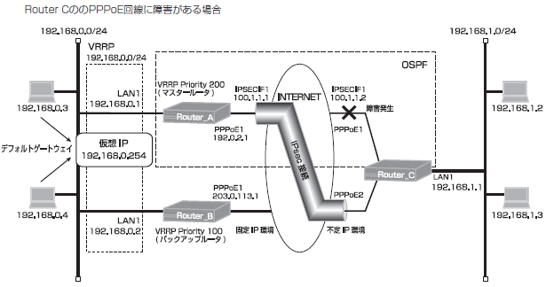
メイン経路で使用しているPPPoE回線に障害が発生した場合を確認します。
PPPoEの接続状態を確認します。(Router C)
| 確認内容 | 画面表示例 |
|---|---|
|
slogを表示 PPPoEが切断されていることを確認 |
Router_C#show slog 0005 0000:16:13.32 2012/02/22 (wed) 10:07:03 5 00000003 08050232 PPPoE1 Disconnected |
PPPoEの取得アドレスを確認します。(Router C)
| 確認内容 | 画面表示例 |
|---|---|
|
PPPoEインタフェースの情報を表示 PPPoEのアドレスが無いことを確認 |
Router_C#show ip interface pppoe 1 PPPoE1 is Down IPv4 is disabled Internet address is not configured MTU is 1454 bytes |
Router Cの経路情報を確認します。
| 確認内容 | 画面表示例 |
|---|---|
|
ルーティング情報を表示 ※1 ※2 ※3 |
Router_C#show ip route Max entry: 10000 (Commonness in IPv4 and IPv6) Active entry:11 (IPv4), 2 (IPv6) Peak:12 Codes: K - kernel route, C - connected, S - static, R - RIP, O - OSPF B - BGP, I - IKE, U - SA-UP, D - REDUNDANCY, E - EventAction A - AutoConfig, > - selected route, * - FIB route, p - stale info. S> * 0.0.0.0/0 [150/0] is directly connected, PPPoE2 S 0.0.0.0/0 [1/0] is directly connected, PPPoE1 inactive O 100.1.1.0/24 [110/1] is directly connected, IPSECIF1, 00:14:22 C> * 100.1.1.0/24 is directly connected, IPSECIF1 C> * 127.0.0.0/8 is directly connected, LOOP0 S 192.0.2.1/32 [1/0] is directly connected, PPPoE1 inactive O> * 192.0.2.254/32 [110/20] via 100.1.1.1, IPSECIF1, 00:04:21 O> * 192.168.0.0/24 [110/20] via 100.1.1.1, IPSECIF1, 00:04:21 S 192.168.0.0/24 [150/0] is directly connected, IPSECIF2 C> * 192.168.1.0/24 is directly connected, LAN S> * 203.0.113.1/32 [1/0] is directly connected, PPPoE2 C> * 203.0.113.254/32 is directly connected, PPPoE2 |
※1:デフォルト宛経路のネクストホップのPPPoE2が有効になることを確認します。
※2:OSPF経路によりIPsecIFの経路が優先されていることを確認します。
※3:バックアップルータ宛経路が非優先であることを確認します。
Router Aの経路情報を確認します。
| 確認内容 | 画面表示例 |
|---|---|
|
ルーティング情報を表示 ※1 ※2 ※3 |
Router_A#show ip route Max entry: 10000 (Commonness in IPv4 and IPv6) Active entry:9 (IPv4), 2 (IPv6) Peak:10 Codes: K - kernel route, C - connected, S - static, R - RIP, O - OSPF B - BGP, I - IKE, U - SA-UP, D - REDUNDANCY, E - EventAction A - AutoConfig, > - selected route, * - FIB route, p - stale info. S 0.0.0.0/0 [150/0] via 192.168.0.2, LAN S> * 0.0.0.0/0 [1/0] is directly connected, PPPoE1 O 100.1.1.0/24 [110/1] is directly connected, IPSECIF1, 00:15:34 C> * 100.1.1.0/24 is directly connected, IPSECIF1 C> * 127.0.0.0/8 is directly connected, LOOP0 C> * 192.0.2.254/32 is directly connected, PPPoE1 C> * 192.168.0.0/24 is directly connected, LAN O> * 192.168.1.0/24 [110/20] via 100.1.1.2, IPSECIF1, 00:05:22 S 192.168.1.0/24 [150/0] via 192.168.0.2, LAN O> * 203.0.113.254/32 [110/20] via 100.1.1.2, IPSECIF1, 00:05:22 |
※1:デフォルト宛経路のネクストホップのPPPoE1が有効になることを確認します。
※2:OSPF経路によりIPsecIFの経路が優先されていることを確認します。
※3:バックアップルータ宛経路が非優先であることを確認します。
Router Bの経路情報を確認します。
| 確認内容 | 画面表示例 |
|---|---|
|
ルーティング情報を表示 ※ |
Router_B#show ip route Max entry: 10000 (Commonness in IPv4 and IPv6) Active entry:5 (IPv4), 2 (IPv6) Peak:5 Codes: K - kernel route, C - connected, S - static, R - RIP, O - OSPF B - BGP, I - IKE, U - SA-UP, D - REDUNDANCY, E - EventAction A - AutoConfig, > - selected route, * - FIB route, p - stale info. S> * 0.0.0.0/0 [1/0] is directly connected, PPPoE1 C> * 127.0.0.0/8 is directly connected, LOOP0 C> * 192.168.0.0/24 is directly connected, LAN S> * 192.168.1.0/24 [0/0] is directly connected, IPSECIF1 C> * 203.0.113.254/32 is directly connected, PPPoE1 |
※:IPsecIFの経路が有効であることを確認します。
設定状態の確認 7
メイン経路で使用しているPPPoE回線の障害が復旧した場合を確認します。
PPPoEの接続状態を確認します。(Router C)
| 確認内容 | 画面表示例 |
|---|---|
|
slogを表示 PPPoEが接続されていることを確認 |
Router_C#show slog 0006 0000:19:27.39 2012/02/22 (wed) 10:10:17 5 000d0003 08050a00 PPPoE1 Connected |
PPPoEの取得アドレスを確認します。(Router C)
| 確認内容 | 画面表示例 |
|---|---|
|
PPPoEインタフェースの情報を表示 PPPoEの取得アドレスを確認 |
Router_C#show ip interface pppoe PPPoE1 is up IPv4 is enabled IP address is 192.0.2.10, subnet mask is 255.255.255.255 Destination address is 192.0.2.254 MTU is 1454 bytes |
Router Aの経路情報を確認します。
| 確認内容 | 画面表示例 |
|---|---|
|
ルーティング情報を表示 ※1 ※2 ※3 |
Router_A#show ip route Max entry: 10000 (Commonness in IPv4 and IPv6) Active entry:10 (IPv4), 2 (IPv6) Peak:10 Codes: K - kernel route, C - connected, S - static, R - RIP, O - OSPF B - BGP, I - IKE, U - SA-UP, D - REDUNDANCY, E - EventAction A - AutoConfig, > - selected route, * - FIB route, p - stale info. S 0.0.0.0/0 [150/0] via 192.168.0.2, LAN S> * 0.0.0.0/0 [1/0] is directly connected, PPPoE1 O 100.1.1.0/24 [110/1] is directly connected, IPSECIF1, 00:18:52 C> * 100.1.1.0/24 is directly connected, IPSECIF1 C> * 127.0.0.0/8 is directly connected, LOOP0 O 192.0.2.254/32 [110/20] via 100.1.1.2, IPSECIF1, 00:02:37 C> * 192.0.2.254/32 is directly connected, PPPoE1 C> * 192.168.0.0/24 is directly connected, LAN O> * 192.168.1.0/24 [110/20] via 100.1.1.2, IPSECIF1, 00:08:40 S 192.168.1.0/24 [150/0] via 192.168.0.2, LAN O> * 203.0.113.254/32 [110/20] via 100.1.1.2, IPSECIF1, 00:08:40 |
※1:デフォルト宛経路のネクストホップのPPPoE1が有効になることを確認します。
※2:OSPF経路によりIPsecIFの経路が優先されていることを確認します。
※3:バックアップルータ宛経路が非優先であることを確認します。
Router Cの経路情報を確認します。
| 確認内容 | 画面表示例 |
|---|---|
|
ルーティング情報を表示 ※1 ※2 ※3 |
Router_C#show ip route Max entry: 10000 (Commonness in IPv4 and IPv6) Active entry:12 (IPv4), 2 (IPv6) Peak:12 Codes: K - kernel route, C - connected, S - static, R - RIP, O - OSPF B - BGP, I - IKE, U - SA-UP, D - REDUNDANCY, E - EventAction A - AutoConfig, > - selected route, * - FIB route, p - stale info. S 0.0.0.0/0 [150/0] is directly connected, PPPoE2 S> * 0.0.0.0/0 [1/0] is directly connected, PPPoE1 O 100.1.1.0/24 [110/1] is directly connected, IPSECIF1, 00:18:51 C> * 100.1.1.0/24 is directly connected, IPSECIF1 C> * 127.0.0.0/8 is directly connected, LOOP0 S> * 192.0.2.1/32 [1/0] is directly connected, PPPoE1 C> * 192.0.2.254/32 is directly connected, PPPoE1 O 192.0.2.254/32 [110/20] via 100.1.1.1, IPSECIF1, 00:08:50 O> * 192.168.0.0/24 [110/20] via 100.1.1.1, IPSECIF1, 00:08:50 S 192.168.0.0/24 [150/0] is directly connected, IPSECIF2 C> * 192.168.1.0/24 is directly connected, LAN S> * 203.0.113.1/32 [1/0] is directly connected, PPPoE2 C> * 203.0.113.254/32 is directly connected, PPPoE2 |
※1:デフォルト宛経路のネクストホップのPPPoE1が有効になることを確認します。
※2:OSPF経路によりIPsecIF1の経路が優先されていることを確認します。
※3:バックアップルータ宛経路が非優先であることを確認します。
All Rights Reserved, Copyright(C) FURUKAWA ELECTRIC CO., LTD. 2012