Requirements for radomes
Currently operational 5G telecommunications has the 3 features of high speed/ large volume, high reliability/ low latency and multiple simultaneous connections. To realize these features, as the communications frequency, the higher frequency, broad submillimeter waveband was introduced in addition to the Sub-6 waveband. In the coming Beyond 5G/ 6G telecommunications, it is expected that an ever higher frequency broad waveband will be adopted.
Material thickness control and angle of incidence adjustment
With telecommunications using high frequency radio waves, although it is possible to achieve high speed communications, the power consumption of each base station increases. In order to limit this power consumption, the radome must allow the effective passage of radio waves. However, the materials typically used for radomes are solid (non-foamed) plastics such as polycarbonate (PC), ABS and glass reinforced PP, and these materials have relatively high dielectric constants and dissipation factors. Given this, when using high frequency radio waves, wave attenuation occurs when passing through the radome as shown in Fig. 1, making it difficult to realize high radio wave permeability.
of radio waves passing through the radome

Radio wave permeability is also impacted by the thickness of the radome. This is because the reflective part of the radio wave interferes when the radio wave enters and exits the radome. Therefore, it is necessary to design the thickness to match the radio wave frequency. However, radio waves do not always enter the radome at a perpendicular angle. When the radio wave enters at an incline angle, the travel distance will differ from the intended design (Fig. 2), making it difficult to achieve the designed permeability. Also, there is concern the use of broader wavebands will result in radio wave permeability fluctuating depending on the frequency. Because it is necessary to address complex issues such as these, radome design is expected to become extremely complicated.

Limitations in relation to base station installation
High frequency radio waves attenuate easily when passing through the radome and transmitted through air. For example, 28GHz radio waves have a range of about 100m, so in order to increase the network coverage area, it is necessary to install base stations at this interval. However, the base station equipment is heavy, and it is difficult to secure suitable locations. In addition, with 5G telecommunications, because the power consumption of the antenna circuit board increases, large heat sinks are incorporated to remove the resulting heat. This is one factor leading to increased equipment weight and the needs for lighter weight.
Given these issues, 5G base stations are required to more effectively transmit radio waves, and the radome housing should use a material with lower dielectric constant and excellent radio wave permeability. Also, in order to enable many base station installations in a wider range of locations at shorter intervals, the radome material should be lightweight. In addition, the radome must be able to withstand the effects of the external environment, including impact resistance, water resistance, weather resistance and fire resistance.
In recent years, an increasing number of sensing devices use high frequencies to increase detection accuracy, including automobile millimeter wave radar and peripheral monitoring millimeter wave sensors. In these applications, too, the radome material is required to have good radio wave permeability, lightweight and resistance against the effects of the external environment.
Advantages of the SCB high performance foam plastic sheets
① Lower dielectric constant (Dk), lower dissipation factor (Df) and reduced weight through foam plastic
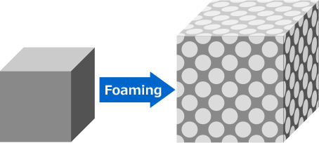
To improve radio wave permeability, as shown earlier in Fig. 1, it is necessary to limit attenuation caused by reflection occurring at the material surface and dielectric loss when passing through the material. An effective solution is the use of a low dielectric material with low dielectric constant (Dk) and dissipation factor (Df) for the radome. The lowest dielectric is a vacuum, and air has similar dielectric properties. Therefore, making the material more akin to air will improve radio wave permeability (Fig. 3).
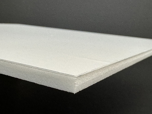
SCB is made by foaming plastic that is already a relatively low dielectric material. It is a high performance foam plastic sheet that achieves reduced dielectric constant (Dk) and dissipation factor (Df) by dispersing air bubbles within the plastic material. Given these characteristics, it should be possible to further increase radio wave permeability. Also, because foaming reduces the density of the material, it will be possible to realize lighter weight.
Air bubbles are dispersed within the base material, resulting in lower dielectric constant (Dk) and dissipation factor (Df)
In this way, SCB high performance foam plastic incorporates our accumulated composition development capabilities and foam technology, and by controlling the dielectric properties (dielectric constant Dk and dissipation factor Df) and foam composition, SCB realizes both excellent radio wave permeability and lightweight.
② Advantages of low dielectric in radome design
Traditionally, solid (non-foamed) plastics have been used for radomes. With these materials, radio wave permeability fluctuates greatly depending on the frequency and angle of incidence. Therefore, guaranteeing good radio wave permeability over the entire frequency band required complex designs and countermeasures. Following the introduction of 5G, as the frequency increases and wave band becomes broader, these problems will become more pronounced.
An effective solution to these problems is to reduce variability in radio wave permeability when each factor changes. This can be realized by decreasing the dielectric constant (Dk) of the radome material and limiting radio wave reflection. With traditional radome materials, it was difficult to control the dielectric constant (Dk), but through the use of foaming technology, it is now possible to realize an overwhelmingly low dielectric constant (Dk) that is unachievable with solid plastics. In addition, by decreasing the dissipation factor (Df), dielectric loss when the radio waves pass through the radome material is reduced, making it possible to realize even better radio wave permeability.
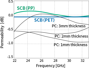
Shown in Fig. 4 is a graph of radio wave permeability in the near millimeter waveband (22-33GHz) as measured by Furukawa Electric. Polycarbonate (PC) was selected as the representative traditional radome material, and radio wave permeability was measured for thicknesses of 1-3mm. As can be seen in the graph (Fig. 4), radio wave permeability changes significantly depending on the thickness and frequency. On the other hand, the graph also shows radio wave permeability for SCB (PET) 1mm thickness (blue line) and SCB (PP) 5mm thickness (green line). Although permeability is somewhat frequency dependent based on the material thickness, radio waves pass through the material with almost no attenuation.

Similar to Fig. 4, shown in Fig. 5 is a comparison of radio wave permeability in the millimeter waveband (75-100GHz). With traditional polycarbonate (PC), radio wave permeability is strongly dependent on the frequency, and it is difficult to obtain high radio wave permeability across the entire broad waveband. However, with SCB, radio waves permeate with almost no attenuation across the entire waveband, regardless of the material thickness.
As indicated above, our original lightweight, low dielectric foam material SCB can be used to obtain excellent radio wave permeability without designing the thickness to match the frequency. This will greatly simplify structural design of the radome.
③ Advantages of SCB when radio wave angle of incidence changes
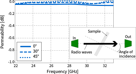
Fig. 6 shows measured radio wave permeability when radio waves are transmitted toward SCB at an angle. Similar to an angle of incidence of 0°, radio waves permeate with almost no attenuation even at an angles of 30° and 45°.
-
(Note)
Figures are from tests conducted by Furukawa Electric
-
(Note)
Measured using the free space method
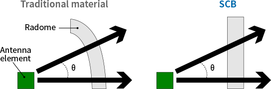
Based on these results, with reference to the positional relationship of the antenna and radome, complex structure designs such as reducing material thickness in certain areas is not necessary. Therefore, using SCB should greatly simplify radome structural design. (Fig. 7)
④ The excellent environmental durability and design flexibility of SCB
SCB is a foam material made using our original technology to foam engineering plastic and super engineering plastic, which are difficult to foam using typical foaming processes. Therefore, it is possible to give the foam material the high performance characteristics inherent to the plastic used. As a result, SCB can satisfy the characteristics required for radomes that are normally difficult for foam materials to satisfy, such as impact resistance, weather resistance, water resistance and fire resistance.
In addition, we have various lineups of SCB based on the required characteristics, and it is also possible to assemble different SCB materials into a layered structure to realize a material unobtainable in the past that has functions in each layer. Because we also possess the technology for form layered materials such as this, we can provide SCB that has been formed in accordance with the various forms required for the radome.
“Smart Cellular Board” and “SCB” are registered Japanese trademarks of Furukawa Electric Co., Ltd.
Our SCB can solve the issues often faced when designing base stations that use high frequency radio waves in 5G/ Beyond 5G/ 6G telecommunications.