Issues and problems in relation to 5G Requirements for high frequency antenna circuit boards
Currently operational 5G telecommunications has the 3 features of high speed/ large volume, high reliability/ low latency and multiple simultaneous connections. To realize these features, as the communications frequency, the higher frequency, broad submillimeter waveband was introduced in addition to the Sub-6 waveband. In the coming Beyond 5G/ 6G telecommunications, it is expected that an ever higher frequency broad waveband will be adopted.
Dielectric loss during transmission (Transmission loss)
With telecommunications using high frequency radio waves, although it is possible to achieve high speed communications, the power consumption of each base station increases. This is because the same high frequency signal passes through the antenna and RF components at the base station, leading to increased impact of dielectric loss (transmission loss) compared to traditional lower frequency signals. In order to limit this increased power consumption, the radome must effectively allow the electronic signals to pass through.
Limitations in relation to base station installation
Radio waves from the antenna tend to have a shorter range as the frequency increases. For example, 28GHz radio waves have a range of about 100m, so in order to increase the network coverage area, it is necessary to install base stations at this interval. However, the base station equipment is heavy, and it is difficult to secure suitable locations. In addition, with 5G, power consumption in the antenna substate will increase, leading to increased heat generation. As a result, huge heat sinks will be installed to remove the heat. This is a major factor in increased equipment weight, resulting in needs for lighter weight.
(Formula)
Dielectric loss = k × f × √Dk × Df
(k: Constant, f: Frequency, Dk: Dielectric constant, Df: Dissipation factor)
Specific gravity and dielectric characteristics of SCB
| SCB base plastic | Specific gravity | Dielectric constant (Dk) |
Dissipation factor (Df) |
|---|---|---|---|
| PET | 0.23 | 1.3 | 0.002 |
| PP | 0.33 | 1.36 | 0.0001 |
| Under development 1 | 0.29 | 1.35 | 0.0001 |
| Under development 2 | 0.18 | 1.2 | 0.0005 |
Based on the above, next generation telecommunication base stations will face the two interrelated problems of increased power consumption due to transmission loss and heavier heat sinks to remove the heat generated due to the transmission loss. SCB will contribute to alleviating both of these two problems.
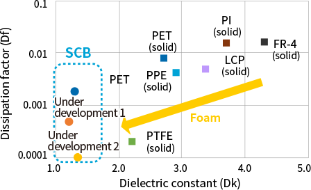
- SCB has excellent dielectric characteristics unattainable with traditional materials.
- Dielectric constant is reduced to a level well below 1.5, and dissipation factor achieves a level of 10-4.
- As indicated in the formula, given the good dielectric characteristics, dielectric loss (transmission loss) of the circuit board will be minimized. As a result, heat generated from the circuit board will be reduced, so it should be possible to reduce the weight of the heat sinks.
- Because SCB is a foam material, it will also contribute to reducing the weight of the circuit board used in base stations.
Advantages of SCB technology, and reduced transmission loss
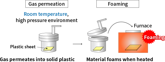
Characteristic manufacturing technology is used to produce SCB.
As shown in the illustration below, gas is permeated into sheet material, and when the material is heated, it foams. Because the material is foamed while remaining in solid phase, it is possible to foam highly heat resistant super engineering plastic, and it is also possible to obtain foam material with even foaming.
Because a high performance, low dielectric plastic can be selected as the base material and evenly foamed, it should be possible to achieve lower dielectric constant and dissipation factor than ever before and reduce transmission loss from the circuit board while maintaining the original features of the plastic material.
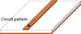
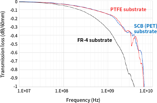
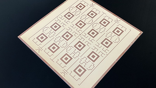
Shown below is a schematic diagram of a microstripline. It was created using SCB-PET as the circuit board for comparison to the traditional FR-4 circuit board and PTFE circuit board used as low dielectric circuit boards. The results of the measured transmission loss (S parameter) are shown in the graph.
This graph shows the measurement results obtained when we evaluated the transmission characteristics. Compared to PTFE circuit board, SCB-PET exhibits similar transmission characteristics. This indicates SCB circuit board has excellent transmission loss reduction effects, and it will also contribute to limiting heat generation.
Formability for SCB printed circuit boards
SCB is a foam material, but it still possesses a thin layer of unfoamed plastic on the surface (skin). Therefore, CCL is possible similar to flexible printed circuit boards using low dielectric plastic films such as PI, PET, PS and COP.
To date, we have made circuit boards using copper cladding and adhering copper plates with an adhesive. Also, because the base material for SCB is a chemical resistant plastic, copper etching is not a problem.
Because a wide variety of plastics can be foamed, SCB has great potential as a low dielectric, high performance printed circuit board material. Please inquire about SCB that can be used for basic circuit board processing methods.
“Smart Cellular Board” and “SCB” are registered Japanese trademarks of Furukawa Electric Co., Ltd.
Our SCB can solve the issues often faced when designing base stations that use high frequency radio waves in 5G/ Beyond 5G/ 6G telecommunications.